
Results and Discussion
Flow Structrue
Since both rear wing designs share the same purpose of producing downforce, the airflow over the main beam follows a similar pattern.

Figure 22 – Streamlines on the old rear wing design (45ms-1 on top, 100ms-1 on the bottom)
Downforce generation of the old rear wing design can be explained through the principle of Newton’s Third Law of Motion. As air flows over the wing (Figure 22), it is deflected upwards and consequently an equal and opposite force is exerted downwards, downforce. At the intersection of the mainplane and the endplates, wingtip vortices are formed. These vortices travel over the wing and descend downwards in the path of a trailing car, influencing its aerodynamics.
The magnitude of downforce increases as the inlet velocity changes from 45ms-1 to 100ms-1, as the higher speeds causes a larger force to be exerted on the wing’s surfaces. This can be observed by the velocity differential from initial velocity to maximum being greater at 100ms-1 with a difference of 71ms-1, compared to 45ms-1 with a difference of 33ms-1. Additionally, both the wing at the bottom of the design and the mainplane experiences a region of near-zero airflow attributed to boundary layer separation happening at the wingtip. As the air flows over the wing, it dips back down attempting to reattach to the wing’s surfaces. This happens as the airflow naturally seeks to balance itself after being disturbed by the wing. This phenomenon doesn’t directly cause more downforce, but it plays a significant role in optimising the wing’s efficiency.

Figure 23 - Streamlines on the new rear wing design (45ms-1 on the left, 100ms-1 on the right).
The airflow dynamics of the new rear wing design exhibit similarities to the previous wing design. Utilising Newton’s Thirds Law of Motion, the upward deflection of airflow generates downforce due to the reactionary forces exerted over the wing. However, the new design priorities deflecting airflow away to the surroundings and out of the path of trailing cars. This secondary purpose causes a reduction in overall downforce generated compared to the old wing. This change is evident with less air being dipping back down behind the wing and therefore less airflow reattaching.
The main vortex coming from this rear wing originates underneath the wing beams, where the slanted edges cause the airflow to remain narrow. Furthermore, a significant region of near-zero airflow is observed above the wing due to its shape encouraging a greater change to the natural path of airflow. This disruption becomes more dominant at higher velocities (Figure 23) where more airflow will be affected.
The evolution of this wing design allows for it to produce less low-velocity airflow in its wake as the airflow recovers quicker. This quick recovery benefit following cars which have cleaner, more predictable airflow to drive through, reducing downforce loss and encouraging overtaking.
Vortices
There are two vortices coming off the back of these rear wing designs, the wingtip and underwing vortex and a lower vortex.

Figure 24 – Vortices on the old rear wing design (45ms-1 on top and 100ms-1 on the bottom)
The vortices generated by the old rear wing design originate at the point where each wing meets the endplates (Figure 24). These vortices are characterised with high rotational velocity and low linear velocity as they form. Travelling downstream, their linear velocity increases while their vorticity decreases. As the inlet velocity increases, such as with the inlet velocity of 100ms-1, these vortices become more dominate and retain their vorticity longer after separating from the wing. At lower inlet velocities, such as 45ms-1, the decrease happens immediately after separating from the wing.

Table 4 demonstrates the relationship between inlet speed, the velocity and vorticity as the greater the inlet speed is the greater velocity and vorticity at both the start and end of the vortex.

Figure 25 - Vortices on the new rear wing design (44ms-1 on top and 100ms-1 on the bottom)
The vortices generated by the new rear wing design (Figure 25) are significantly weaker than that of the old rear wing design. With the lack of a bottom wing, the lower vortex dissipates, Whilst the top vortex has a much larger shape. This is due to its lower rotational speeds causing the vortex to expand quicker and lose energy. This rapid expansion reduces its effect on the trailing cars performance as the vortex has less disruptive strength. The top vortex assumes a straighter path compared to the last wing design, keeping the vortex away from the path of a following car.

The difference in vorticity for the new rear wing is smaller than the difference for the old rear wing, this goes in hand with the velocity for the new wing being lower (Table 5). The vortices coming off the new rear wing give less momentum to the surroundings and therefore receive less linear velocity in return, hence why the change in vorticity magnitude is smaller.
Vortices generated by these rear wing designs initially exhibit higher vorticity and low linear velocity. As these vortices detach from the wing, their angular velocity (vorticity) decreases while their linear velocity increases. This phenomenon can be explained through the interplay of energy dissipation and momentum conservation within the airflow. As the vortices move, viscous forces within the air act to dissipate their rotational energy and therefore reducing their angular velocity. However, not all energy is lost; some is redistributed into the linear motion of the surrounding air, thereby increasing the overall velocity. Despite losing this rotational energy, the airflows momentum must be conserved.

Equation 3 presents the equation for momentum conservation, which applies to the vortices generated in the wing designs as they redistribute momentum within the wake. As vortices expand and dissipate, their rotational momentum disperses into the surrounding airflow. In return the freestream airflow transfers linear velocity back into the vortices. This dynamic interaction respects momentum conservation.
Vortices play a vital role in aerodynamic performance of these wings by increasing downforce, wake stability and energy redistribution. Comparing Figures 24 and 25 highlights that the vortices produced by the old rear wing design are stronger, thereby enhancing airflow behaviour in four keyways:
- Vortices stabilise airflow over and around the rear wing, ensuring that the pressure distribution remains constant. This allows the wing to produce a larger amount of predictable downforce.
- Vortices extend and strengthen the low-pressure regions, increasing its pressure difference between the top and bottom surfaces.
- Vortices delay boundary layer separation, keeping the flow attached to the wing for longer. Flow separation reduces pressure control and disrupts the wings effectiveness, so reducing it maximises downforce generation.
- Vortices can guide and organise airflow behind the wing, reducing wake turbulence. A cleaner wake can indirectly improve downforce by reducing drag.
All these reasons give evidence to explain the better performance of the old rear wing design in generating efficient downforce compared to the new design.
Furthermore, vortices significant effects the aerodynamic performance of following cars. Rear wing vortices contribute turbulent air to the wake, when a following car enters this region, the turbulence can reduce the effectiveness of the front wings surfaces as they struggle to generate consistent downforce. This disturbed flow increases aerodynamic resistance, therefore resulting in greater drag. The severity of these effects is dependent on the distance between the vehicles; closer proximity increases the wake’s impact, reducing stability and grip whereas the effect diminishes as distance increases. This dynamic creates challenges during chasing and overtaking, as the following car experiences reduced performance. The new rear wing design addresses these issues by minimising vortex strengths and consequently turbulent wake, improving driving conditions and encouraging overtaking.
Flow Seperation
Airflow separation occurs in both rear wing designs due to similar aerodynamic principles. When pressure increases along the flow direction, the fluids velocity decreases, resulting in a loss of kinetic energy. If the energy diminishes too far, the fluid is unable to overcome the adverse pressure gradient, leading to flow separation. The angle of attack for rear wings is typically high in order to generate lots of downforce, but the steep gradient further contributes to flow separation.
This flow separation can be seen in Figures 26 and 27 where the wall sheer stress reaches 0 below the wing. Wall shear stress is a measure of the frictional forces exerted on each surface of the wing, so as the value decreases less airflow is attached to the wing.
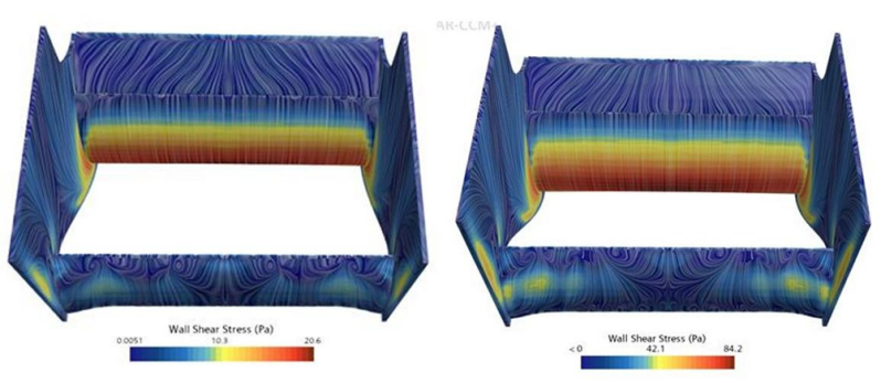
Figure 26 – Wall sheer stress behind the old rear wing designs (45ms-1 on the left and 100ms-1 on the right)
Flow separation for the old rear wing design (Figure 26) primarily occurs towards the trailing edge of the main wing, resulting in reduced airflow behind the upper wing. Additionally, separation is observed across the middle section of the lower wing and partially along its sides.
The old rear wing design is more prone to flow separation compared to the new design, largely due to the complexity of its geometry and interaction with oncoming airflow. Its configuration, comprising of multiple flaps and sharp edges, induces abrupt changes in airflow paths. These sudden changes lead to a more turbulent wake with unpredictable separation patterns. The main objective of the old wing design is to maximise downforce generation, employing steep angle of attacks and flat elements that inherently promote flow separation.
Chaotic flow separation, whilst typically undesired due to its unpredictability, can indirectly contribute to increased downforce. Chaotic separation can create areas of significant pressure instability, increases the pressure difference between the upper and lower regions of the wing. With flow separation being unpredictable, it can result in irregular patterns of flow reattachment. This can be seen in Figure 26 on the bottom where there are dots of increased friction. These reattachments stabilise small regions of airflow, increasing the aerodynamic effectiveness of certain wing sections and contributing to downforce.

27 – Wall sheer stress behind the old rear wing designs (45ms-1 on the left and 100ms-1 on the right)
The new rear wing design separates right across the underside of the beam (Figure 27). This flow separation happens very early under the wing but happens in a very organised manor as the airflow doesn’t get attached to the endplates allowing for a simple separation.
The new regulation rear wing design uses smoother geometry with a continuous structure to enhance airflow management and reduce chaotic separations. By generating a controlled wake with reduced turbulence, these designs facilitate stable flow separation. The curved endplates support smoother airflow transitions, achieving a balance between downforce generation and stability while operating with greater aerodynamic efficiency.
Flow separation presents significant challenges for trailing cars. The disturbed airflow reduces the effectiveness of the front wing’s aerodynamic components, leading to a loss in downforce and diminished grip. This reduction in grip hampers the ability of following cars to maintain maximum performance, required to overtake. Drivers often compensate this performance loss by overexerting their tires, which results in elevated temperatures and increased degradation. Furthermore, the turbulence from flow separation may obstruct airflow to vital cooling systems, such as radiothons and brakes, reducing their ability to maintain lower temperatures and function at peak efficiency.
Generating Downforce
The velocity difference across the wing plays a key role in producing downforce as it aids in the creation of a pressure difference. The wings shape (inverted aerofoil) causes the air to accelerate below the wing and resulting in a higher velocity.

Figure 28 – Velocity Vector across the symmetry plane for the old rear wing design
(45ms-1 on top 100ms-1 on the bottom)
The old rear wing design (Figure 28) encourages airflow velocity to accelerate under the wing, following the curve like structure, whilst decelerating over the wing. For the old rear wing design, the steep curvature of the surface causes the airflow to achieve higher velocities, which leads to irregular, chaotic flow separation. This velocity change and flow separation leaves behind an area of limited airflow, which can be seen as the airflow velocity reaches behind the mainplane.

Figure 29 – Velocity Vector across the symmetry plane for the new rear wing design
(45ms-1 on top 100ms-1 on the bottom)
For the new rear wing (Figure 29), early flow separation causes a much larger region of limited airflow as the two velocities have greater distance to cover until they connect. Along with this, the area of low velocity in the wake of the wing is reduced massively, demonstrated by how quickly the airflow returns to its inlet velocity after the wing. The new rear wing design encourages lower velocities, producing less downforce compared to the last wing. This reduction in downforce minimises the extent of the un-energised airflow in the cars wake. Consequently, the airflow returns to its natural state much quicker, promoting more efficient wake management.
The velocity difference across the rear wing plays a crucial role in downforce generation as it establishes a pressure difference across it. This is in accordance with Bernoulli’s principle, expressed mathematically as:

Using equation 4, the height (h) is negligible as flow is approximately at the same vertical level and air pressure (𝜌) and, gravity (g) is constant at 1.229kgm-3 and 9.81N respectfully. Consequently, equation 4 of a rear wing provides us with a pressure (P) and velocity (v) relationship:

From this relationship (equation 5), it can be inferred that higher velocity above the wing decreases pressure, while lower velocity below the wing increases pressure. The pressure differential generates the downward force, known as downforce.
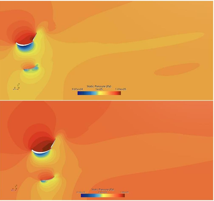
Figure 30 – Pressure distribution across the symmetry plane for the old rear wing design
(45ms-1 on top 100ms-1 on the bottom)
For the old rear wing design (Figure 30), there is a considerable pressure build above the wing and pressure drop below it. This substantial pressure differential is considerably greater than that of the new rear wing design (Figure 31), reflecting its main purpose in generating maximum downforce. The enhanced downforce comes at the cost of aerodynamic efficiency, as the configuration of the wing creates an expansive region of low-pressure airflow in the car’s wake, known as dirty air. This dirty air greatly effects the aerodynamics of the trailing car which has to use this low-pressure unenergised air, reducing their performance.

Figure 31 – Pressure distribution across the symmetry plane for the new rear wing design
(45ms-1 on top 100ms-1 on the bottom)
With the new rear wing design (Figure 31), the concept limits the downforce generated by reducing the pressure difference, in order to clean up the wake behind the car. The lower pressure region is very spread unlike the intense and well-defined low-pressure region of the old wing. Consequently, the wake behind the car is shown to return back to a normal state much quicker, reducing the dirty air behind.
The difference in downforce generated between the old and new rear wing designs illustrates a shift in aerodynamic priorities, aligned with the recent regulatory changes. The new design produces less downforce as formula one transitions into a ‘ground-effect era,’ where the majority of downforce is generated beneath the car. This shift enables the rear wing to focus on minimising the turbulent wake left behind the car. Therefore, the energised, low-pressure, low-velocity airflow that disrupts the front wing of the following car is much smaller and manageable. The turbulent air produced by the new design is directed upwards and outwards, away from the path of trailing cars.
Aerodynamic Forces
Rear wings generate a variety of aerodynamic forces, with downforce and drag being the two most prominent. These forces are intrinsically linked, as an increase in total downforce typically leads to a corresponding increase total drag. Rear wings are designed to maximise downforce, ensuring optimal performance and stability which comes at a cost of large amounts of drag. For these wings to be efficient, the generated downforce must outweigh the aerodynamic penalties imposed by drag. Formula One cars usually have enough power behind them to push through the drag penalties in order to utilise running the wing.

Figure 32 – A force (N) over position (m) graph for the old rear wing (45ms-1 on top 100ms-1 on the bottom)

Table 6 – Results from Figure 32
The old rear wing design produces more downforce and drag than the new rear wing. Table 6 shows the downforce generated across one streamline over the symmetry plane of the wing. From Figure 32 we can see the wing produces the most drag at the initial contact with airflow and reaches peak downforce around the point where the high pressure meets the low pressure behind the wing. Along the symmetry plane, the wing reaches a max downforce of 60.51N at 45ms-1 inlet speed and 333.21N at 100ms-1 inlet speed.

Figure 33 – A force (N) over position (m) graph for the new rear wing (45ms-1 on top 100ms-1 on the bottom)

Table 7 – Results from Figure 33
The new rear wing design has higher drag then downforce at two points, when the airflow meets the bottom wing and when the airflow meets the top wing (Figure 33). As the endplates do not encase the wings, they have an overlap where the two corners of the upper wing are visible, causing more friction and therefore drag. This wing design also produces most its downforce at the trailing edge where the two different pressure zones meet. The maximum downforce produced at inlet speed 45ms-1 is 29.91N and at 100ms-1 the most downforce produced is 159.89N.
This demonstrates that between the two wing designs there is a difference of 30.6N and 173.32N for both inlet velocities. This is around a 50% decrease in maximum downforce generation with the new regulation rear wing.
Conclusion
The 2022 regulation changes to the rear wings design effectively addresses the primary objective of reducing dirty air, fostering closer racing, and encouraging overtaking opportunities. The previous rear wing design created substantial low-pressure, un-energised airflow that negatively impacted trailing cars by reducing their downforce, stability, and grip. To address these issues, the updated regulations imposed stricter requirements on wing geometry, limiting design complexity. The simplified structure of the new rear wing reduces turbulence by promoting smoother airflow around the wing. Key differences such as revised endplate designs, minimise wingtip vortices and decrease interference with trailing cars, allowing them to maintain aerodynamic performance. Additionally, the new rear wing effectively manages wake by redirecting it upwards, keeping dirty air away from following cars.
Despite these aerodynamic improvements, the new rear wing design produces less downforce, primarily due to reduced vortex generation. Vortices play a crucial role in enhancing downforce by increasing the pressure difference across the wing and delaying flow separation. The old rear wing optimised these effects to maximise performance. However, the reduction in downforce aligns with the transition towards the ground-effect era. The car’s underfloor becomes the primary source of downforce, using compressed airflow underneath the car to create a low-pressure zone. This effect, combined with high pressure above the car produces a suction force that keeps the car pulled down to the ground. The emphasis on ground-effect aerodynamics complements the aerodynamic updates of the new rear wing, fostering more exciting and competitive racing.
However, allowing cars to follow each other much closer does not always inspire overtaking, particularly for midfield cars which experience DRS trains. These occur when multiple cars follow closely, with all but the leading car using DRS. In these scenarios, the advantage of DRS is neutralised, hindering drivers’ ability to progress through the field. The unintended consequence opposes the regulations’ wider goal of enhancing viewer excitement. To mitigate this issue, an increase to DRS angle is proposed, as it would enhance its efficiency and reduce time taken for a car to overtake before a build-up occurs. This adjustment could help alleviate the formation of DRS trains, ensuring more dynamic racing.
The new rear wing achieves its intended goals by reducing dirty air and creating more sustainable racing conditions. The updated design represents a significant step towards competitive racing, allowing trailing cars to perform more efficiently and conserve fuel and grip when overtaking.
Allowing for more racing moments to occur in a race and boosting viewer entertainment.
It is essential to acknowledge the limitations of these results. Simulations were conducted as isolated wing components, which does not fully represent their maximum performance. The overall vehicle design, including the body and diffuser, influence how the airflow interacts with the wing to optimise its performance.
By Dean Jarrett
All research presented was conducted at the University of Leicester in 2025 as part of my final‑year individual project. The project was awarded a First‑Class classification, achieving 79/100 for the written report and 72/100 for the presentation.
Qualifications: Degree of Bachelor of Engineering (Aerospace) with the award of Second Class Honours (Upper Division).
@Deano-J@outlook.com
Create Your Own Website With Webador